Thinking: How to make Ambilight clone for Raspberry ?
Very long title… but worth reading if you plan to make ambilight clone for your LED TV. After a few days of "hard work" I will try to make complete guide what RGB diodes and software to choose and how to solve all traps while trying to make Ambilight for you LED TV!
Idea
Idea is to add LED RGB strip behind your LED TV that will change colours according to video that your player (Raspberry Pi) is playing. Why? Because you can :) and it is easier for your eyes at night.
Software for Ambilight Arduino Raspberry clone
Raspberry Pi OS
First there is some "fresh" information. XBMC is now called Kodi. Basically it is part of the software responsible for multimedia playing. If you have stand alone PC hardware you can install it additionally to you operating system. But if we are talking about Raspberry Pi, most reasonable is to choose distribution (SD card image) that comes with preinstalled XBMC. Now there are several options:
- Raspbmc available here: http://www.raspbmc.com/index.html In last month it was announced that project is closing down, but it is stable, all plugins work so still it is valid option
- OSMC (Open Source Media Center) is new OS that inherits Raspbmc. It is available here: https://osmc.tv It boots very fast and has fresh look. Alpha version that we tested are not yet stable (that's why they call them alpha) but it looks very promising. Bad news that there is no support for Boblight, and good news that they will support Hyperion. So you can check their progress.
- OpenElec – RECOMMENDED – you can get image for your SD card here: http://openelec.tv/get-openelec It is very stable, supports Boblight and it is possible to add Hyperion too. Only drawback – you can not change root password easily (?!)
Software for LED backlight
Basically we have two major options: Boblight or Hyperion They have slightly different approaches, while Boblight consisting of daemon – server (boblightd) and XBMC boblight plugin as client. Plugin is responsible for all calculations (grabs edge pixels of screen) and serialises all data to boblight daemon that then sends all data to your Arduino "driver". This has big drawback – impact on your CPU and mayor issue – lag, and we want RGB lights running lightning fast!
Boblight XBMC client + Boblightd daemon
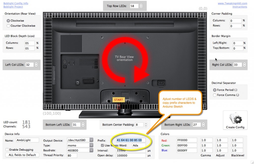
Nevertheless Boblight could be viable solution for some systems, and I have found very good guide and info about boblight setup here (Thanks Hans!): http://www.tweaking4all.com/home-theatre/xbmc/xbmc-boblight-openelec-ws2811-ws2812/ Hans also made fantastic utility for making boblight configuration files : http://www.tweaking4all.com/home-theatre/xbmc/boblight-config-maker/ Be sure to check it even if you are going Hyperion way, because his utility can help you calculate initial prefix bytes, but more on that in Arduino section.
Why choose Hyperion?
For start it is newer and more promising. But here are some real advantages:
- It is very fast (almost no delay compared to almost 1sec lag with boblight)
- Priority channels – while you are watching video you can use mobile app to override colors or play effect!
- Did I mention mobile app for iOS ?
Check up-to-date wiki here: https://github.com/tvdzwan/hyperion/wiki 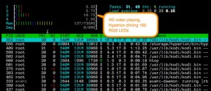
How to install Hyperion?
Login to your SSH on OpenElec (You must enable it first in system settings services. Username "root" password "openelec") and type:
curl -L --output install_hyperion.sh --get https://raw.githubusercontent.com/tvdzwan/hyperion/master/bin/install_hyperion.sh

sh ./install_hyperion.sh
Detailed installation guide available here
Hyperion JSON configuration
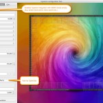
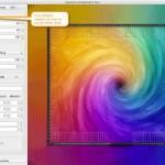
You can be guru and write your own config file, or just get and use latest Hyperion JSON configurator utility here or
grab jar
What about LED placement?
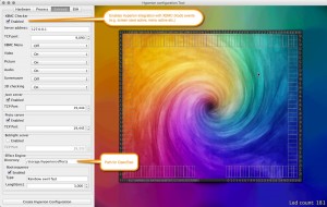
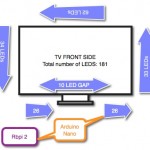
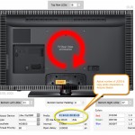
Here is sketch of my LED placement. Keep in mind in what direction are you putting LED strip, count number of leds from each side, top, bottom, and gap if you have it. 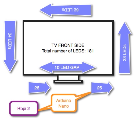
How to make config file?
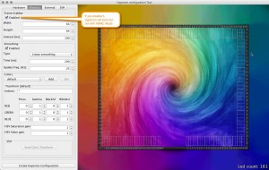
Config file for Hyperion is .JSON file. They made a nice java utility, so use it to generate first config file, upload it to your Raspberry (using SCP) or just copy paste it to shell and than make some fine tuning in shell editor like "nano". Detailed information here 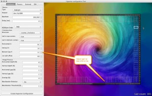
How to change Hyperion configuration or troubleshoot?
If setup is not working, first check if the hyperion is running by typing:
ps -a | grep hyper
It it shows process and it is stalled you can kill it and stat Hyperion again with:
killall hyperiond /storage/hyperion/bin/hyperiond.sh /storage/.config/hyperion.config.json </dev/null >/dev/null 2>&1 &
If you want to see and debug hyperion messages run it instead with (omiting suffix of previous command):
/storage/hyperion/bin/hyperiond.sh /storage/.config/hyperion.config.json
There is an easy way to test it using one of shell commands below (for solid colour or Rainbow effect):
/storage/hyperion/bin/hyperion-remote.sh --priority 50 --color red --duration 5000

/storage/hyperion/bin/hyperion-remote.sh --effect "Rainbow swirl fast" --duration 3000
If it still does not work you can always edit configuration, adjust it,
nano /storage/.config/hyperion.config.json
Remember that hyperion must reload configuration so kill hyperion and start it again as explained above
Hardware for "RGB delight"
What RGB diodes to choose?
There are many options for RGB LED strip. Idea is to have controlable one – to be more specific RGB diodes that you can individually control. So be careful while you are ordering your 5m pack. What model should you choose? I was thinking about WS2801, WS 2811, WS2812, WS2812b. Keeping it short, you should go for WS2812b IP65.
Why choose WS2812b with IP65 and 3M stick tape, 60 leds/m?
Advantages:
- They use just 3 wires! +5v, GND and DATA line.
- WS2812 have chip integrated in 5050 RGB diode!
- WS2812b have reverse voltage protection (it is easy to mix two wires and kill LED strip if you do not have b version)
- IP65 gives you silicone over diodes, I like that more than IP67 (plastic tube). It is good that your LED strip is protected from dust etc.
- 3M stick tape helps you to stick the diodes direct to TV (if you are less brave and would like to make frame, check some websites)
- they come in 3 variants 30LED, 60LED or 144LED / m. I think that 60LED/m provide optimal brightness.
WS2812 main drawbacks:
- Hard to controll It can not (or can but it is not easy to do) be controlled directly from Raspberry Pi2! You must use Arduino. Why? Because it needs 800kHz signal and your Raspberry Pi is not running realtime OS, so any interrupt will brake the timing and cause problems and unreliable behaviour
- Expensive You can expect price per m about $12. (March 2015.) If you find lower price, double check that they are really 60 LED / m. That LED type is 5050, and that they have 3M stick tape and silicone water protection (IP65)
Update April 2017.: Price is now better for WS2812b, you should be able to find 5m 60LEDs/m IP65 for $30 + shipping. (Stanislav, thanx for tip on price change) - They need lots of power at 5V DC supply on packaging bag they are stated at 90W. But for 5 meters 10A 5V will be enough. I have measured 3A to 5A while all 5m were on. If you have shorter length maybe 5A supply will be enough. Max power calculation is 5m x 60 LED = 300 LED. each LED is 3 separate colors (Red Green Blue = RGB) so 3x 20mA. Total 300x60mA=18A current. Voltage 5V (beware not to use 12V!!) Giving total power 18A * 5V = 90W ! Have in mind that equivalent of regular bulb wuould be multiplied by e.g. 7, so max brightness would give you 90W * 7 = 630W (advice: do not stare directly at your LEDs!)
Hardware for player
Simple: Choose Raspberry Pi 2!
There are many options available now. If you have Raspberry Pi 1 you should probably think about new Raspberry Pi 2 because it have more memory and as they say it have 6 times faster CPU! You can consider any other PC capable or running XBMC (now called Kodi). I have tested Bannana Pi, and Banana Pi Pro, but they have problems with software support for embedded hardware video acceleration. So with those models you can expect problems while playing (software decoding) full HD video material.
What Arduino to choose for Ambilight (Adalight)?
Simple: Whatever you have, or order cheap Arduino Nano!
Beware! There are some project that suggest direct connection of Raspberry Pi to Arduino via serial pin (RX TX) or SPI. Some arduinos are working with 5V logic level and Raspberry is using 3.3V and you will probably require TTL logic level shifters.
Connection type between Raspbery Pi and Arduino: USB!
There are some projects suggesting that if Raspberry sends signal via RX TX pins they will be safe for Arduino but you should not risk if the Arduino sketch opens pin for output and gives 5V to 3.3V compliant Raspberry GPIO. The safe way is to connect them with USB cable (micro for Arduino Leonardo, mini for Arduino Nano or stanrad USB for Arduino Mega)
How to setup connection ?
When you connect Arduino Nano to Raspberry it will be detected as /dev/ttyUSB0. If you use Arduino Mega it will be /dev/ttyACM0. How to check that? Just login via SSH to your Raspberry and type: ls -al /dev/tty* which will give you something like:
crw--w---- 1 root tty 4, 8 Jan 1 1970 /dev/tty8 crw--w---- 1 root tty 4, 9 Jan 1 1970 /dev/tty9 crw-rw---- 1 root dialout 204, 64 Jan 1 1970 /dev/ttyAMA0 crw-rw---- 1 root dialout 188, 0 Mar 28 18:52 /dev/ttyUSB0
you will see ttyUSB0 or ttyACM0 and then you will know what to enter in config files. If your USB serial is missing you can re-plug Arduino. You can always check with command: dmesg which will give you result like:
[ 70.912700] usb 1-1.3: new full-speed USB device number 9 using dwc_otg [ 71.032687] usb 1-1.3: New USB device found, idVendor=0403, idProduct=6001 [ 71.032724] usb 1-1.3: New USB device strings: Mfr=1, Product=2, SerialNumber=3 [ 71.032741] usb 1-1.3: Product: FT232R USB UART [ 71.032756] usb 1-1.3: Manufacturer: FTDI [ 71.032771] usb 1-1.3: SerialNumber: AH01KPB9 [ 71.072351] usbcore: registered new interface driver usbserial [ 71.072562] usbcore: registered new interface driver usbserial_generic [ 71.072696] usbserial: USB Serial support registered for generic [ 71.092861] usbcore: registered new interface driver ftdi_sio [ 71.092992] usbserial: USB Serial support registered for FTDI USB Serial Device [ 71.093405] ftdi_sio 1-1.3:1.0: FTDI USB Serial Device converter detected [ 71.093584] usb 1-1.3: Detected FT232RL [ 71.094575] usb 1-1.3: FTDI USB Serial Device converter now attached to ttyUSB0
What about Raspberry Pi Arduino USB serial port speed? Use 500.000 !
You must set the same speed in Hyperion (Boblight) configuration and in your Arduino Adalight sketch! Usually standard speed are multiply of 9600 like 115200, 230400, 460800 but it will generate problems for your Raspberry/Arduino! In our tests 115200 work ok, but it could probably be slow (just multiply necessary bandwidth e.g. 300 LEDs, each 3 colors, 1 byte per color, 30 fps … So you will probably need higher speeds. But you boblightd or hyperion will loose connections. Faster Arduinos will work better (eg. Mega can work at 230400, Arduino Due even better), but after lots of hours lost it looks like 500000 is best option. Why? Because it is multiply of CPU frequency and there are no lost clocks. 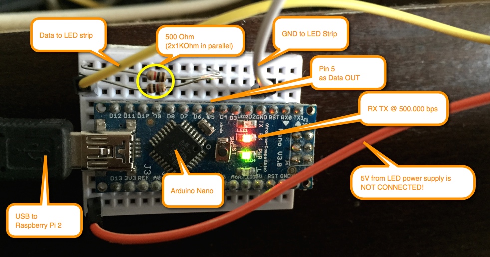
What about Arduino sketch?
Thanks to Hans Luijten here is the script that I have slightly modified here. Idea is to use Arduino to simulate "Adalight" device. Relevant part:
#include "Adafruit_NeoPixel.h" // DEFINITIONS #define STARTCOLOR 0x333333 // LED colors at start #define BLACK 0x000000 // LED color BLACK #define DATAPIN 5 // Datapin choose what you want or that is available #define LEDCOUNT 181 // Number of LEDs used for boblight 178 B1 E4, 180 B3E6, 181 B4E1 (iz boblight conf -1 tj 180), 182 B5E0 #define SHOWDELAY 200 // Delay in micro seconds before showing default 200 #define BAUDRATE 500000// Serial port speed, 460800 does not work – tested with Arduino Mega, Nano, Leonardo but 500000 is working with Nano #define BRIGHTNESS 70 // Max. brightness in % const char prefix[] = {0x41, 0x64, 0x61, 0x00, 0xB4, 0xE1}; // Start prefix ADA char buffer[sizeof(prefix)]; // Temp buffer for receiving prefix data
These last two lines are usually deal braker if you are not carefull. If you look at Hyperion code for device type "Adalight" :
_ledBuffer[3] = ((ledValues.size() – 1) >> 8) & 0xFF; // LED count high byte _ledBuffer[4] = (ledValues.size() – 1) & 0xFF; // LED count low byte _ledBuffer[5] = _ledBuffer[3] ^ _ledBuffer[4] ^ 0x55; // Checksum
You will see that it reads configuration file and that last two values (0xB4, 0xE1) are required for my number of LEDS (first 0 last 180, totall 181 LEDs) 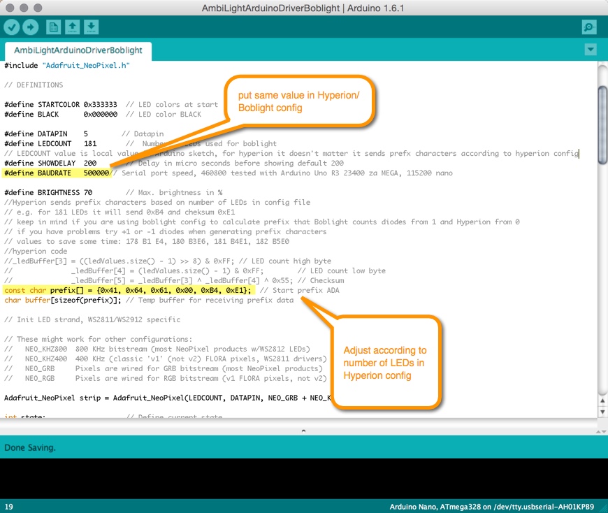
How to connect WS2812b to your Arduino?
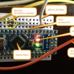
In the previous Arduino sketch we have defined pin 5 as Data output pin. Signal should go through 480 Ohm resistor (in next segment there is explanation why the resistor is there) and then to RGB LED strip Data in pin. Remark: It DOES matter what end of led strip you use. There is marked Data IN and Data OUT pin for each led. Also, another recommendation: We have connected Arduino to Raspberry Pi over USB. It provides 5V to power Arduino. We should not connect 5V from LED strip. Idea is to "divide" RGB LED strip power supply from Arduino to avoid power supply problems for Arduino (we do not want to think about purity of 5V on LED strip). Conclusion: only two wires are connecting Arduino and LED strip. GND (ground) and pin 5 over resistor that carries data signal for diodes.
Why use resistor?
According to scheme, data OUT pit should not be connected directly to Arduino. Signal should go through 480 Ohm resistor. If you wonder why we not use some capacitor, remember that signal on data pin is 800kHz, and capacitor in series would block DC signal, and if used in parallel will distort square signals of zeroes and ones. If you put resistor it will attenuate peak levels… but that's not that we want. Purpose of resistor in series is that resistance of LED strip is much higher than Arduino output pin. Idea is to use resistor to balance impedance of both ends because of refracted signal. If you do not have 480Ohm (like me) remember that you can use e.g. two resistors of 1KOhm in parallel that would give you about 500Ohms. Exact value is not mandatory.
Troubleshoot Hyperion
When you plugin Arduino via USB to Raspberry, all LEDs turn on and stay that way. You can see /dev/ttyUSB0 or /dev/ttyACM0 but Hyperion is not working.
You must enter same communication speed and setup device type to "adalight". Also double check that two initial bytes in Arduino sketch are appropriate for number of LEDs in your hyperion config. Refer to Arduino sketch section.
Hyperion is working (command line test plays some effect or colour) but when you play movie LEDs are not resembling edge colours.
Probably Hyperion is not communicating with XBMC (Kodi). You do not need to install any plugin like with boblight but you must enter proper ip and port 9090 in hyperion config. Also Kodi must listen on port 9090. You can check that with: rbp2:
~ # netstat -lnp | grep tcp | grep 9090 tcp 0 0 :::9090 :::* LISTEN 352/kodi.bin
Also doublecheck that System > Settings > Services: UPnP tab : Allow control of Kodi via UPnP Remote control : Allow programs (on this system and on other systems) to enable. Optionally turn off/on this settings and restart if necessary.
USB Serial port is missing when you type ls -al /dev/tty*
Replug Arduino USB cable. Check if Arduino LED is on. Sometimes Raspberry does not detect Arduino after restart. Comment if you have any idea?
Idea for future upgrade
Now everything works nice while you are playing video from your Raspberry Pi. If you play some content from e.g. Apple TV or game on your Sony Play Station then you can either choose some static colour or video effect from Hyperion library. But… there is even better solution for that… get some USB video grabber (composite or HDMI if your budget can support it). Connect it to your multimedia center (Raspberry Pi) and use it to grab signal while playing form external device over HDMI cable to you LED TV. More about that when video grabber arrives…
Gallery for OpenElec Hyperion/Boblight RGB LED project
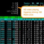
- Raspbery Pi 2 running OpenElec and Hyperion CPU usage
UPDATE 2019:
Thanks to Raspori, here is the updated script where you do not need to enter a prefix, it will be automatically calculated. The only data that you need to update is your number of LEDs and data pin – that you have chosen. Here is the sketch:
New Hyperion Ambilight Arduino sketch



Can’t wait to try this with my tv. Awesome article, thanks !
hey there, i have a problem. when i connect hdmi splitter, tv resolution goes down from 1080p to 576p and i cant change it. is this problem familiar to others, are there any solutions? with this resolution my 65″ tv is totally useless. please help
Hmm, try to change cables / splitter? This is not related to Ambilight/Hyperion… probably splitter is not good (active/have power supply)
Hello,
i got a problem with this and can´t fix it. My Arduino don´t get any command from the RPi2. The Baudrate is in both Files the same as in your Instructions. Also my Nano is connected via USB0. My Hyperion is working when I sent a command like an effect, I can see via SSH the effect but my LED's won't show anything. I hope you can help me. I uploaded the two files on pastebin if you want to see them.
hyperion.config.json
http://pastebin.com/4MMSZSV4
ArduinoAmbilightAdalightSketchHyperionBoblight.ino
http://pastebin.com/5BCNg7RX
I hope you can help me.
Thanks in advance.
Greetings from Germany
Marcel
Many thanks to the Admin. I forgot to edit the Prefix in the Arduino Sketch.
Thanks
Hi Marcel,
have a look at comment in Arduino:
// values to save some time: 178 B1 E4, 180 B3E6, 181 B4E1, 182 B5E0
and check line:
const char prefix[] = {0x41, 0x64, 0x61, 0x00, 0xB7, 0xE2}; // Start
prefix ADA
in short, depending on the number of LEDs in config, you should adjust
last 2 values…
try like this:
const char prefix[] = {0x41, 0x64, 0x61, 0x00, 0xB5, 0xE0}; // Start
prefix ADA
The prefix part is real weird… I have a 300 led strand that I can’t get working and i think it is because of the prefix. Bobligt configurator gives me the string “41 64 61 01 2C 78” and that’s not at all what I’m expecting and it’s not working. I’ve tried to find a way to calculate the checksum but I just can’t find anything. Maybe you can help?
How do you calculate the checksum?
Ok figure it out.
_ledBuffer[5] = _ledBuffer[3] ^ _ledBuffer[4] ^ 0x55; // Checksum
example B4 E1
B4 in Binary = 1011 0100
0x55 in Binary = 0101 0101 // now XOR them and you get
E1 in Binary = 1110 0001
You also Xor them with Low LED but if its zero you can ignore it.
Glad that you have figured it… Answer is always in source of Hyperion :)
Did I correctly calculate this prefix? 154 LED’s {0x41, 0x64, 0x61, 0x00, 0x99, 0xCC}
Hi everyone,
Is it possible to do this with WS2801 LEDs?
yes, but they use 4 wires and different protocol for communication.
Hi
I am going to build exactly the same project! And I hope you have only positive feedback having it up and running.
May I ask you please about your power schema for LEDs 5 meters long?
I am worrying about the maximum possible current which goes thru LED strip – 5V and 90W mean 18A!!!
So if you connected the power to one side of the LED strip so it could be very heavy stress on thin power lines along with the LED strip!
What was your approach? Did you connect 5DC power to only one side of the strip? Or maybe you connected the power at many points after each meter? Did you care of it?
Privet Alex,
yes I am very satisfied with setup. I have tested 5m of WS2812b and they used from 3A to 4A… keep in mind that this is average :)
I think that if you limit brightnes to 70% it will not go over 4A. I am using 12A 5V AC DC power brick, connected only to one side. What you should care is maybe to use diode for protection of first LED.
Hi,
Thanks for a very comprehensive tutorial. I got my ambilight running with Rpi 2 with xbmc along with Arduino R 3. However I never got hyperion running so I ended up with Boblight which was far easier. However I want to get this running with any video source (xbox/ blu ray). Could you please help with the code required to modify the boblight config file to accept usb as a video source.
Thanks in advance.
hi APT! I have found that boblight lags to much for me, so decided to setup Hyperion… If you are interested in Bobligh have a look at friends website: http://www.tweaking4all.com/?s=Boblight
Wonderful article jovan.. There is just one doubt.. Can u pls explain the schematics or circuit diagram of the resistor connections u made? I am not that familiar with circuits. Also can we simply connect the leds to arduino? I have seen tutorials where they are connected directly to the arduino?
Hi Rishi, for circuit diagram, for now, check my friends website : http://www.tweaking4all.com/hardware/arduino/arduino-ws2812-led/
Hello
I’m trying to set it up – i have 10+15+25+15+10 ws2812b led – so it is 75. I calculated prfix to 0x4A, 0x1F. But … it does not work :( Leds light up at the beging as startcolor is set up, but then nothing happends. I notice that there is no TX/RX activity on Arduino – also when i plug in ftdi serial converter it does not light up any tx/rx led. Both a detected as /dev/ttyUSB0. IMHO something is wrong with hyperion it self.
Of course if i use Arduino Serial Monitor everything works ok – leds a light up during data exchange.
What a shame … i made it but there was my mistake. I edited /storage/hyperion/config/*.json instead of /storage/.config/hyperion/*.json. It works but you have to use prefix calculated for one less led. I use 30led/m and have 75 – but prefix had to be calculated in boblight config maker for 74 leds.
Yap, calculating prefix can make problems, that’s why in comments I suggested trying +1 or -1 on the actual number of LEDs. Glad that you hyperion now works :)
There is one more catch up. Boblight config maker shows TV rear side, while Hyperion Config shows front side. In my case i made a mistake and checked counter clockwise. Funny effect when you see mirror view of ambilight :D
:) I can only imagine …
One more question why did you set max brightness to 70% and you use show delay set as 200ms? What was purpose of this settings. Why not 100% and why not shorter delay?
70% is because:
– I use 10A 5V ACDC power supply, so wanted to be sure not to overload it
– it is more than enough for my room
Don’t remember about 200ms, but it is initial delay so really doesn’t matter, probably wanted to be sure that there is enough time to initialize
Hi Jovan,
I have the same project but with the Arduino Uno r3 with rpi b+ and I cannot be able to get it work.
My shell command test is
/storage/hyperion/bin/hyperion-remote.sh –priority 50 –color red
–duration 5000
Connected to localhost:19444
Set color to 255 0 0
#############################
Application build time: Mar 6 2015 20:57:44
QCoreApplication initialised
Selected configuration file: /storage/.config/hyperion.config.json
ColorTransform ‘default’ => [0; 175]
Device configuration:
{
“colorOrder” : “grb”,
“name” : “MyPi”,
“output” : “/dev/ttyUSB0”,
“rate” : 460800,
“type” : “adalight”
}
Opening UART: /dev/ttyUSB0
Black border threshold set to 0.01 (3)
Not creating any smoothing
Effect loaded: Knight rider
Effect loaded: Blue mood blobs
Effect loaded: Cold mood blobs
Effect loaded: Full color mood blobs
Effect loaded: Green mood blobs
Effect loaded: Red mood blobs
Effect loaded: Warm mood blobs
Effect loaded: Rainbow mood
Effect loaded: Rainbow swirl fast
Effect loaded: Rainbow swirl
Effect loaded: Snake
Effect loaded: Strobe blue
Effect loaded: Strobe Raspbmc
Effect loaded: Strobe white
Initializing Python interpreter
Hyperion created and initialised
run effect Rainbow swirl fast on channel 0
Boot sequence(Rainbow swirl fast) created and started
XBMC video checker created and started
terminate called after throwing an instance of ‘std::runtime_error’
what(): Json server could not bind to port
Aborted
My Hyperion Config Json File
http://pastebin.com/CKPcbNBZ
My Arduino Sketch
http://pastebin.com/DALn3SJd
Thank you for a great guide and support.
Junior
Problem is that your port is not available:
so either kill already running hyperion, or check what app is bind to that port using shell command
I killed it and XBMC finally connected. but the LEDs don’t show up. :( Or the problem could be with the prefix configuration? I have 176 LEDs in my build. I’m new to OpenELEC and HTPC so please suggest me.
###############
XBMC Connected
Message from XBMC: {“id”:666,”jsonrpc”:”2.0″,”result”:[{“playerid”:1,”type”:”video”}]}
XBMC checker: switching to VIDEO mode
Message from XBMC: {“id”:668,”jsonrpc”:”2.0″,”result”:{“System.ScreenSaverActive”:true}}
Message from XBMC: {“id”:667,”jsonrpc”:”2.0″,”result”:{“item”:{“file”:”/var/media/HIREN_USB/Zathura.A.Space.Adventure.2005.m-720p.CtHts.mkv”,”label”:”Zathura.A.Space.Adventure.2005.m-720p.CtHts.mkv”,”type”:”unknown”}}}
Message from XBMC: {“id”:670,”jsonrpc”:”2.0″,”result”:{“version”:{“major”:15,”minor”:2,”revision”:”02e7013″,”tag”:”stable”}}}
effect finished
Message from XBMC: {“jsonrpc”:”2.0″,”method”:”GUI.OnScreensaverDeactivated”,”params”:{“data”:{“shuttingdown”:false},”sender”:”xbmc”}}
Message from XBMC: {“jsonrpc”:”2.0″,”method”:”Player.OnSeek”,”params”:{“data”:{“item”:{“title”:”Zathura.A.Space.Adventure.2005.m-720p.CtHts.mkv”,”type”:”movie”},”player”:{“playerid”:-1,”seekoffset”:{“hours”:0,”milliseconds”:0,”minutes”:0,”seconds”:-20},”speed”:1,”time”:{“hours”:0,”milliseconds”:0,”minutes”:0,”seconds”:0}}},”sender”:”xbmc”}}
Message from XBMC: {“jsonrpc”:”2.0″,”method”:”Player.OnPlay”,”params”:{“data”:{“item”:{“title”:”Zathura.A.Space.Adventure.2005.m-720p.CtHts.mkv”,”type”:”movie”},”player”:{“playerid”:-1,”speed”:1}},”sender”:”xbmc”}}
Message from XBMC: {“id”:666,”jsonrpc”:”2.0″,”result”:[{“playerid”:1,”type”:”video”}]}
Message from XBMC: {“id”:667,”jsonrpc”:”2.0″,”result”:{“item”:{“file”:”/var/media/HIREN_USB/Zathura.A.Space.Adventure.2005.m-720p.CtHts.mkv”,”label”:”Zathura.A.Space.Adventure.2005.m-720p.CtHts.mkv”,”type”:”unknown”}}}
Message from XBMC: {“id”:669,”jsonrpc”:”2.0″,”result”:{“stereoscopicmode”:{“label”:”Disabled”,”mode”:”off”}}}
one more problem when i try the shell command of RED color it shows GREEN color instead.
/storage/hyperion/bin/hyperion-remote.sh –priority 50 –color red
–duration 5000
Connected to localhost:19444
Set color to 255 0 0
If your setup mixes RED & Green you could always fixit in Arduino sketch, e.g. line:
strip.setPixelColor( currentLED++, buffer[0], buffer[1], buffer[2]); // and assing to LEDs
try something like:
strip.setPixelColor( currentLED++, buffer[0], buffer[2], buffer[1]); // and assing to LEDs
just an idea…
Components ordered pi2, arduino nano, WS2812B, 5V 10A supply wish me luck :)
Michal, wish you best luck and that delivery is fast! :)
I come here to thank you! my project is working perfect im very amazed how nice it works! i had some problems but i resolve them pretty fast.
Used aluminim strip to make frame but i was surprised that LED strip dont have covered bottom contacts so i dont use 3M tape as i was scered of short circuit ( what you think? is it safe to use?). Now ill study about setting hyperion and play with colors maybe. Thanks for brightness setting!In dark room even 70% is too high for my girlfriend (in sunlight its just perfect with 70%) so ill adjust this a bit even lower. BTW i add capacitor in 5V and resistor for data line as you suggest.
im sad about poor android app to control but better this then nothing :)
LEDs have delay but its fast enought to not notice it in real use.
Here are some photos. ill add more maybe video in near future. You can have a look at blue arduino nano case i made from USB doctor case :)
https://goo.gl/photos/dCJM7sX2HD2apmK57
I had fun with this project i learn a bit of arduinos and will continue reading how to get the most of ambilight :) Will happy to see more articles from you :)
Glad to hear that shipment was fast and that everything works!
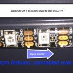
Hmm… my LEDs have insulator (transparent glue over diodes and stick tape at bottom) picture here:
http://ai.rs/wp-content/uploads//2015/03/RaspberryPiArduinoHyperionAmbilight_WS8212b_LedStrip.jpg
I think they should be safe to glue on alu frame or as I have did, directly on my TV :) I have just reinforced additional stick tape on corners and few other places.
Yap 70% brightness is really bright :)
Have not tried Hyperion android app, but IOS is very good! find it here:
https://chaosspace.de/hyperion-remote
Very nice photos and tidy setup! I like blue arduino nano case, where have you found it?
Ill measure it for but it look like it have naked connecting point at bottom side where 3M is.Maybe i should stick it to aluminium frame after all as it will get some cooling from aluminium too.
I made case for nano from USB doctor here http://goo.gl/mM4LNu it cost 1€ and it still works without case :) . I justmade one hole for microUSB conector and it fit perfectly. Nano need cut here and there but it was finished in a moment.
BTW: I guess there is no way to make LED response faster right? :) just curious
Great idea for Arduino Nano case! Just ordering 2pcs :)
Hyperion is pretty fast compared to Boblight… what is the serial port speed that you have set? Try 500.000 ? I think delay with that is hardly noticeable…
Im glad i help you with case idea :) yes i have 500.000 but it was only first moment i was focusing on it..Its fast enought now!
Watching original philips ambilight videos and i think this project is way better then original ambilight by philips :)
I have new idea to make light sensor whish will dinamicaly change brightness or just simply turn ambilight OFF in daylight and ON in night. Maybe its simple as add light sensor and include it to code but idk if im experienced enought to code it :) will definitely google for this. Here are a lot info about this http://www.tweaking4all.com/forums/topic/boblight-add-ambient-light-detection/
BTW: here is video boring as video but awesome if you see it in real https://www.youtube.com/watch?v=F2cwklK0plE
Nice video, and yes I see small delay (I think that I have the same delay) but it is ok for me :)
Thought about making sensor to auto adjust brightness,it is really simple to do, but IOS app is soo good, I usually use it to set up brightness of “Warm mood blobs” effect that I use as a background light… You can change brightness without tweaking Arduino code, just go to “Transformations” tab in mobile app and setup e.g. Gamma values little lower. Hardware solution with sensor could be even better, but for know, my next tweak would be using EasyCap to have Ambilight for external HDMI sources (e.g. Apple TV that I use for Netflix)
you are right hyperion app is very nice i just find out that i can tweak it on the fly for ambilight not just static all solid colors :) i use it for tweak colors and then edit hyperion.config.json to make it permanent. I must say colors and movie atmosphere is now a lot more natural its fantastic now!
If someone is interested i change this values (others default)
HSV
saturation 0,9
value gain 0,7
Threshold
RGB to 0,02
Whitelevel
Blue 0,7
about sensor i want use it not for dinamic change brightness but to ON and OFF whole ambilight setup.In very bright sunlight OFF in night ON. It should be very easy problem is that if i make it AdjustBrightness()” in the “loop() it can slow down arduino other way is check for light only when i turn on kodi..so it will be needed to reboot for refresh light status :-/ Will test it very soon. code is simple i think i understand it.
Thank you, hope that your Hyperion settings will help for new “Ambilight Raspberry” fans.
I still use default settings…
nice setup, i have looked at your images you shared and saw at the end a potentiometer hooked to arduino nano? You use it to control the brightness? can you share more details how to do? Also what capacitor in 5v you have added ? for what?
Thank you.
Thnx Vlad, I do not have any potentiometer, these LED strip (WS2812b) are digitally controlled and you cannot dimm them by potentiometer, you can dim them from hyperion or by setting max brightness in arduino sketch.
Also there is no capacitor, I have explained why you can not use capacitor, if you mixed capacitor and resistor (which is not good :green: ) read section “Why use resistor?”
Thanks jovan, I saw the potentiometer at michal post and in the images he posted here https://goo.gl/photos/dCJM7sX2HD2apmK57
He probably used potentiometer instead of resistor… which is bulky solution but works ;)
Hi All,
Ordered!
What is the delta if i wish to use my minix neo z64 android running kodi 15.2 instead of the Rpi2?
Is it a simple installation on the android?
Thx!
Hi Idan, probably should work under Android as long as you can instal Hyperion and setup configuration properly. Will eventually try myself on some android box (looking now at GeekBox TV)
sorry, i think i’m being really thick. i have everything set up. the android app tells me everything is “synchronised” and i think the only reason my pi is not talking to my arduino is down to my complete inability to work out the last two value in my prefix. I have 115 LEDs. 31 up each side and 53 along the top. 115 in total. I’ve tried using a decimal to hexadecimal converter but that just gives me a 73!!? I can understand your example because 180 LEDs converts to B4 but what’s the E1? Thank you for any pointers. I was hoping to get this up and running for a film tonight (New Year’s Eve). Please can someone help me with my numbers? Cheers, Don
Hi Don, try calculating prefix for + or – 1 diode. In your case instead of 115 LEDs, try 114 or 116…this because first is 0 not 1, then last would be 114 instead of 115. Hope that movie that you choose for NY night is very good one and you ambi light works! Enjoy!
Thanks but it’s actually calculating the prefix that i just don’t understand. I’m presuming I’m missing some sort of logic or maybe I’m just tired but i have no idea after reading the instructions again and again. If someone can tell me what my values should be and maybe another explanation of how they got them would be fab. Please, thank you. :)
HNY
OK, so I think I worked it out but it’s still not working even if I go +1 or -1 on the LEDs.
115 LEDs .. 115 in hexadecimal is 73 (binary is 01110011).. so my first prefix is 0x73 ?
XOR binary of 73 with binary of hexadecimal 0x55 (01010101) gives me my second hexadecimal value 26 ?
So my prefix is : {0x41, 0x64, 0x61, 0x00, 0x73, 0x26} – or 0x72 and 0x1d for 114 LEDs or 0x74 and 0x21 for 116 LEDs ?
I have tried all of these but to no avail.
My Hyperion is running.
I can connect to it via my android App.
When I plug the nano in all the LEDs light up quickly one by one along the thread.
My TX LED on the nano is flickering like crazy but nothing else is getting through to the LEDs apart from the initial light up…
output of /storage/hyperion/bin/hyperiond.sh /storage/.config/hyperion.config.json is [here](http://pastebin.com/CGe6MVDn)
arduino sketch is [here](http://pastebin.com/6HX4S5Ls)
hyperionconfig file is [here](http://pastebin.com/9Dv1P1aS)
if anyone has 5 minutes to take a look for me I would be really appreciative. I’ve spent 5 hours fiddling with this again today and it’s making me cranky :) Thank you.
Don, do LEDs light at all (initial running light pattern) ? This should work even if Arduino is powered up and connected to LEDs (even without Raspberry).
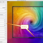
For Hexdecimal prefix, Can you try downloading Boblight config app and use it to calulate prefix? (this one: screenshot )
What was the movie lastnight? :)
Hi Jovan and thank you very much for your reply. I’ve done as you suggested (Boblight configurator is very handy!). I tried the prefix at my number of LEDs and +1 and -1 but still not joy.
The LEDs (WS2812b’s) do always light up and always show the correct number too (I’ve tried a longer string and some remained unlit) but the Pi does not seem to actually be able to get data through to them despite activity on the Arduino’s TX LED. Something definitely gets to the Arduino because the LEDs light up a couple of times as the Pi boots and then then the TX LED becomes active. I can’t think of anything else that I can amend. I’m going to try Boblight and see if I run into similar problems / lag unless you have anything left as a suggestion.
The film was “Kingsman, The Secret Service”. If you haven’t watched it already, it’s an excellent film! Cheers, Don
yeah, weird… Boblight worked first time…. ? ? ?
Have you solved it? BTW Nice movie (Kingsman)
hi. not yet and I ran out of tinkering time over the weekend and am now back at work :(
hopefully i’ll get the chance to play with it again this week (once the kids are in bed) but i’m not too sure what else to look at next apart from a reinstall of openelec for starters. boblight works but it’s not as responsive as I’d like so I am definitely going to persist with my quest for hyperion!
i disabled boblight again and went back through everything on hyperion and now it work. i don’t think i changed anything from before but it started first time. thanks for bearing with me. sorry i can’t add any pointers for others apart from persistence :)
I’m off to watch The Man from UNCLE now :)
Good news! If you find what was the problem, please share…
PS Movie UNCLE is a good one, and music too! :)
Thanks for this good tutorial!!! Main problem for me was to find this bloody prefix , I have tried different combination +/- 1 and finally found that for actual 144 LEDs I need to use 143 LEDs in Boblight configurator. This was the only problem (5 hours !!!), in rest was very smooth.
By the way if you want to switch on/off Abilight from TV’s RC you need to do 2 simple steps:
1) vi /storage/hyperion/bin/toggleHyperion.sh
#!/bin/bash
if [ `ps -a hyperion | grep hyperiond | wc -l` = 3 ]
then
killall hyperiond
else
/storage/hyperion/bin/hyperiond.sh /storage/.config/hyperion.config.json
2) vi ~/.kodi/userdata/keymaps/ambilight.xml
XBMC.System.Exec (“/storage/hyperion/bin/toggleHyperion.sh”)
3) Reboot
Hi, i got problem with programing arduino uno (clone), always i got this message in log:
HyperionBoblight.ino:34:58: warning: narrowing conversion of ‘249’ from ‘int’ to ‘const char’ inside { } [-Wnarrowing]
const char prefix[] = {0x41, 0x64, 0x61, 0x00, 0xF9, 0xB0}; // Start prefix ADA
HyperionBoblight.ino:34:58: warning: narrowing conversion of ‘176’ from ‘int’ to ‘const char’ inside { } [-Wnarrowing]
from boblight config i get this prefix: 41 64 61 00 FA AF
i try it convert with binary calculator….
can you plz found my mistake?
thanks
Hi Riddle, try +1 -1.. for number of LEDs? Read comments Evghenii had similar problem
Thank you for such detailed post. Still have an question: why Arduino was included into this project? Have checked post few times but can’t found answer on this question. Is it just “driver” for LED strip?
Hi Vladimir,
as I have mentioned, WS2812b diodes are hard to control directly from Raspberry Pi2! You must use Arduino. Why? Because diodes need 800kHz signal and your Raspberry Pi is not running realtime OS, so any interrupt will brake the timing and cause problems and unreliable behaviour. You can say that arduino is used as “driver” ;)
Yeah, now it’s clear! Thank you Jovan for explanation. I have found many different (cheap or easy or …) installations but always returning to this issue: Raspberry will work unstable, will freeze, will “think” so much time. Or it requires some additional modules like logic levels converters… So, waiting for my parcels from China and will start! Thank you for your efforts!
Arduino is cheap, with tutorial it is easy, so yeah this one is also cheap and easy but it will work and you’ll get custom ambilight :)
PS regarding flash, I really hate it but would like to see your posts…so please don’t be lazy :)
BTW Nice blog, pity that you are using flash for images/videos…
Thank you! :-) Yeah, it used for Youtube clips. Need to modify it but is it possible to beat laziness? :-)
Great step-by-step guide! One question… I want to use this, but instead of using RPi2 as a media player, I want to use this on my Windows-based HTPC running Kodi. Do I just plug in the Arduino directly into the PC and configure Hyperion through Windows?
You can plugin Arduino to other device (not Raspberry Pi) but then you must access serial port differently.
I do not know if hyperion can work on Windows, but you can check project page here: https://github.com/tvdzwan/hyperion/wiki/installation
Anyway I suggest you to order Raspberry Pi (2 or 3) and dive into the wonderful world of linux/embedded computing.
I think I found a solution… http://raspberry-at-home.com/control-lightberry-from-kodixbmc-htpc-over-network/
It looks like I would need to have Arduino connected to RaspPi then to HTPC. Kodi would then control Hyperion on RaspPi over network. Seems like a big mess of devices to get this to work… could you also post a wiring diagram for for connecting all devices?
Hey man,
This is really a terrific tutorial. There are a few out there but you really have put it all together very nicely, so thanks for that. I am running into a couple of issues with my config and have not been able to get my head around it however.
:(
This is my set up:
Raspberry Pi 2
Arduino Mega
WS2812Bs (240 LEDs)
I have set the appropriate baud rates (500000) in the configs and the sketch, when the Arduino fires up, the string of LEDs lights up in white coming on one at a time all the way to the end of the strip, but then nothing else happens.
Hyperion is running and I can see the RX led on the arduino oscillating like crazy so I know its receiving data from the PI, but when I send it commands the LEDs do not respond. I have tried changing my LED count by one pixel up and down, and have gone back to the drawing board with the config a few times (getting my prefix from Boblight config maker). For 240 LEDs I am using the following prefix:
const char prefix[] = {0x41, 0x64, 0x61, 0x00, 0xEF, 0xBA};
I can see my commands come through in the debug when I send hyperion remote commands from the IOS app and from the shell, but I dont see this translated into effects. I have also tried the other sketch that I have seen out there using the fastled libraires and the result is similar with the exception that I get the red-green-blue solid, after which I get nothing.
I have read a ton of posts on this and have tried a number of things to no avail. I feel like there is something right in front of me that perhaps I am missing so I thought that I would try my luck by posting my issue here.
Any insights that you folks can share would be greatly appreciated. My wife is not a huge fan of the tv being propped up on the coffee table in the middle of the living-room all weekend. lol.
My Arduino sketch and Hyperion config is below.
Thanks in advance!
My sketch:
http://pastebin.com/PVNLWS3g
My hyperion Config:
http://pastebin.com/tSRudKgz
Best,
Amos
Hi Amos,
try changing prefix as if you have +1 -1 for number of LEDs? Read comments Evghenii had similar problem
Hey Jovan,
Thanks for getting back to me.
Really strange thing.
So when I changed the Serial speed from 500000 to 460800, and it worked. The fast rainbow effect ran and I was able to send SSH commands to the hyperion daemon, changing, colors/effects, etc.. But then after attaching to it from the hyperion IOS app. It stopped.
Then I changed the baud to from 460800 to 230400. Again it worked when I started Hyperion on the PI but then it stopped. So I just purchased another 5meter WS2812b strip just to validate the connectivity and configurations. I still just have it all connected to the whole strip because I have pulled my TV off the wall like 3 times.
lol, My wife wants to kill me!
I am fairly technical but this one has me stumped.
Have you ever heard of anything like this?
Best,
Amos
Hey Jovan,
Thanks for getting back to me.
Strangest thing, so I changed my baud from 500000 to 460800 and boom. I got the rainbow effect and was able to send effect commands over SSH to the PI and see the result.
I connected the IOS app and was able to do the same, but then the SSH commands stopped working. And no matter what i did (rebooting, resetting), nothing worked . So I then again changed the baudrate to 230400, and again, I got the initial rainbow effect but then it would not accept other commands.
So I am wondering if maybe I have an issue with my 480k resistor on the data input to the arduino?
Because my wife was ready to kick my butt for having the TV off the wall for two weeks, I just purchased a new WS2812b strip for testing to figure this out. After which I will just move the whole thing over.
I am fairly technical so this is a little frustrating for me. Is there a way to debug the serial connection in real time on the arduino? I googled this but really could not find anything that I could grab on to.
Have you ever seen anything like this? Seems like it should either work or it shouldn’t don’t you think?
I AM IN LED PROJECT HELLLLLLLL! LOL!
It looks like that you loose sync from arduino to diodes. They are receiving data at 800KHz and they are time sensitive – eg if signal goes out of sync they stop working – remember only time component is used to determine which LED should receive data.
First, I recommend experimenting before glueing on TV (wife factor / risk mitigation :) )
Secondly, I think that you should try to replace arduino? I use very cheap Arduino Nano (and now experimenting with ESP8266 – google for it, fantastic device). There is a reason why I have recommended 500.000 baud rate (because it is multiply of Arduino clock). I have experienced similar problems with other baud rates…
PS is itgenx your setup? maybe we should connect on linkedin ;)
Hey Jovan,
Yeah the clock multiple resonates. I have a maybe 4-5 Arduinos lying around. A couple of Unos and Megas, I will swap that out and report back.
I am relatively new to embedded devices and while I have developed some light coding chops over the years, machine logic is a bit of a different animal than I am accustomed to. Processing algorithms and all this talk of precise timing is somewhat intimidating to a novice like myself.
That being said, its really interesting stuff, I have pretty much replaced all the major lighting in my place with LED bulbs (Soraa mainly as I think they are the best quality retail halogen replacement on the market). This is my first project using programmable LED strips, but the Soraa bulbs and lighting automation I have done to date has saved me at least 30% on my electric bill. So now as you can imagine I am addicted.
I also recently purchased a SmartThings hub and have been using IFTTT to bridge the gap between systems that do not integrate directly . I have all kinds of little projects I want to take on but I wont let myself until I get this done!
Yes ITGenX is my setup :). I took a regular “jobby job” for a couple of years but now I am back to consulting. Its a grind but the pay is better. :)
I am afraid a monster has been created!
You know,
I realized that I neglected to mention another thing. The ultimate trajectory of this project is to be able to take the HDMI output on my receiver and split it between the PI and the TV the way some other folks have done.
This is secondary of course to getting the basic pieces working as you have described. So I have not considered that perhaps there was something about my configuration that potentially contributes to the challenge as well.
So I have a video grabber on the PI that I use to capture the video and send it over the serial connection to the Arduino. This is nothing new as many folks seem to have successfully done this. More so with the 2811 strips it seems but there are a few that have done it with the 2812Bs as well.
I thought I should throw that out there in case having the USB grabber in the PI maybe changes things. I don’t see how it would but folks with more experience may have know of a specific gotchya in my scenario.
Definitely hit me up on Linkedin as well! I am always up for expanding my network!
Hey Jovan,
Ok so I got it going but I had to do a couple of things differently.
First thing I did was take your advice and swap out that fickle Mega for the Uno. Initially it was the same result with the whole LED strip glowing white, and then doing nothing else.
I did try moving the LED count up and down by one but that was not getting me there either. So as with all things when I am stumped I leaned on google and started looking around at how some other folks were doing this with their projects, and I noticed that there were two basic camps for the Arduino sketches. Some folks were using the Neopixel sketch libraries while others were using the FastLED library based Sketches.
Looking at the code of the FastLED sketches, I found that I liked it better because of the way it handled the prefix configuration.
The Neopixel based sketch was using the Hex values with the XOR ‘d checksum while the FastLED Sketch used what I think is a slightly more elegant approach.
The NeoPixel Sketch prefix:
const char prefix[] = {0x41, 0x64, 0x61, 0x00, 0xef, 0xba}; // Start prefix ADA
The FastLED sketch prefix:
uint8_t prefix[] = {‘A’, ‘d’, ‘a’}, hi, lo, chk, i;
I also needed to set the color order for my WS29812Bs to GRB.
After doing those things, everything started to work. I even tried dropping the same Sketch back on the Mega but it didn’t work which basically tells me that you were correct in your assertion that it was not working properly.
Below is my working FastLED Arduino Sketch..
http://pastebin.com/2L9ZBhYe
Thank you so much for taking the time to share your experiences with us all. You make it SO much easier for the rest of us.
:)
Best,
Amos
Hi Amos,
glad that I have helped you and that your “Ambilight clone” is now better then original :)
Apologies, I thought that my post didn’t go through so I created two with basically the same info.
np, i have approved both (they were slightly different)
Hi, thank you for the guide, it was very detailled.
I have a question about the resistor. I didn’t use one, because i didn’t have one and the leds looked fine when i have connected the wire to the arduino.
And now, after the data welding, the stuff works fine but sometimes the leds “flash”
Do you think that the flash is due to the lack of resistor ? I don’t really know electronic stuff.
Yes, resistors are really cheap and you should use one to avoid flickering…
quote from guide: ” Signal should go through 480 Ohm resistor. If you wonder why we not use some capacitor, remember that signal on data pin is 800kHz, and capacitor in series would block DC signal, and if used in parallel will distort square signals of zeroes and ones. If you put resistor it will attenuate peak levels… but that’s not that we want. Purpose of resistor in series is that resistance of LED strip is much higher than Arduino output pin. Idea is to use resistor to balance impedance of both ends because of refracted signal. If you do not have 480Ohm (like me) remember that you can use e.g. two resistors of 1KOhm in parallel that would give you about 500Ohms. Exact value is not mandatory.”
Hey Jovan,
I was really excited when I found this tutorial. I was looking into making an ambilight, and you’re tutorial is exactly the setup I’m after. I’ve already got a Pi3 running Kodi (openelec) and I’m currently in the process of ordering the rest of the parts. Per your recommendation, I’ve found a suitable strip of LEDs, but I have a question pertaining to the power supply. I’ve read through your notes, and you mention that your setup maxes out around 3-5amps when all the leds are on.
With this in mind, do you think it would be alright to power a 5m (may be cut down a little) with a 5V 8A power supply? Or would that not be enough?
Also, do you know if there is any advantage to using a power supply with a metal case and terminals, versus using one in a black plastic case? Just curious.
Again, a fantastic tutorial. Thanks!
Thanks!
Hi Matt,
glad that tutorial helped you… Raspberry Pi 3 is even better ;) Regarding power supply, I have measured 3 to 5AMPs for 5m… keep in mind if you limit brigthnes to e.g. 70% (believe me – more than enough) you will limit maximal current also… So 8A will be more then enough. Personally I have both Power supplies, with metal case and terminals and black plastic case. For my living room plastic one looks less industrial, an if you accidentally spill something I think it is safer ;) But metal perforated case of course is better to cool down power supply – but I think that is really not mandatory in this case… Anyways, I recommend that you test setup for a few hours before gluing everything to TV and hiding in “cable forest” behind TV :)
Hey Jovan,
Have created my setup! And first of all – thank you for your great tutorial!
But it not works well:
1. I have installed Hyperion in OpenElec and configured OpenElec as it described here.
2. I have created Hyperion config hyperion.config.json with Java tool and stored it on OpenElec.
3. I have restarted OpenElec.
4. I have customized Arduino sketch (with calculations of number of LED and check sum with this code). I have 185 LEDs in stripe:
#include
int main( int argc, const char* argv[] )
{
int LEDS=185, LEDHigh,LEDLow,LEDCheck ;
LEDHigh = ((LEDS – 1) >> 8) & 0xFF;
LEDLow = (LEDLow – 1) & 0xFF;
LEDCheck = LEDHigh ^ LEDLow ^ 0x55; // Checksum
LEDS = LEDS -1;
printf(“LEDS: %d\n” , LEDS );
printf(“LEDHigh: %d\n” , LEDHigh );
printf(“LEDLow : %d\n” , LEDLow );
printf(“LEDCheck : %d\n” , LEDCheck );
printf(“LEDS in HEX : 0x%x\n” , LEDS );
printf(“LEDCheck in HEX : 0x%x\n” , LEDCheck );
}
On OpenElec restart LED plays Rainbow Swirl fast (I hope that is it. ;-) It looks like LEDs lighting in sequence). After that – I can’t receive any activity: I have tried to play video, to switch effect via Android Hyperion App., to use console tools from Hyperion. No results. :-(
I see that Hyperion receives my requests and even indicates that finished with it execution, but no activities on LEDs.
All setup works well. Strip is blinking if I use default LED-related sketches in Arduino. OpenElec runs movies and Hyperion indicates that sees this activity.
Could you please give me an hint?
Hi Vladimir, try +1 -1 for number of LEDs? (Beacuse LED are counted from 0 not from 1) Read comments, Evghenii had similar problem. Hope this helps? Or share your solution
Yeah, thanks! Found it! Problem was in control sum. I have tried to recalculate prefix in boblight configuration tool and found it. And yes, +/-1 LED is very good hint too!
Now it works brilliant!
Thank you and others in this post again for such detailed instructions!
Next ideas to work now: how to pause kodi when I have switched off my TV? ;-)
Glad that it works now!
Regarding you idea to automate Raspberry when switching TV on/off, try googling keywords “raspberry cec hdmi”
Hi Jovan,
Thanks for the nice tutorial! I got everything functioning, but when I ran some test video’s green image on my tv showed red on the led strips and red image on tv showed green on led strip, blue was fine. So I thought this was going to be an easy one and changed the color order from GRB to RGB in the hyperion config maker but after this change hyperion didn’ work anymore, so i changed the value in the sketch as well but was still not functioning. I reverted everything back to GRB but no luck. The only way I seem to got it working again was by re-applying the sketch in your tutorial and changing all the values again. I must note that the initial led light up when plugging in the arduino kept working. Does the color order value needs to be the same in the sketch and hyperion config? I Have absolutely no clue why I cant get it working again by changing the values to what they were, do you have any idea?
Best Regards,
Joren
best Regards,
Joren
You just need to change two colors, but it looks if raspberry stop communicating with arduino that you should check also your init string?
You mean i do not have to correct this issue by changing the color order via RGB GRB values? I will check the init string, but seems strange to me, it wasn’t changed. Thanks for the quick reply btw.
Thank you for the great tutorial. It took a bit of work but I got it working perfectly on Pi3 running OSMC with an Arduino mega. The mega has some problems so I used the FastLED sketch from Amos (http://pastebin.com/2L9ZBhYe) and it worked perfectly.
Owen, I am glad that it helped you, so that there is one more member in Ambilight Raspberry family :)
BTW I have compared our solution with latest Philips model, and first impression is that it is better then original (more leds per meter, ability to use as ambient light when TV is off, bottom side LEDs – 4 sides instead of just 3…)
I have an issue that is different from the ones above. So my setup is fairly large. Well 747 LED for what I am doing. I am using the fastled sketch. I can get the whole system to work on a test string of 16 LED and 200 LED with an Arduino Uno. It works great. Unfortunately there is not enough memory in an Uno to run such a large number of LED. I have a mega and am swapping out the code as the person has done above but the light will not active.
.
I am 100% sure that Hyperion is running as it runs the Uno. I am sure the script is fine as it works on the Uno. I believe its a connection issue between the Pi and the Arduino Mega. When I plug the Mega into a PC. It plays a red, green, blue effect and then goes dark. It does this every time it’s plugged in. The Uno does the same thing. It does the same thing when plugged into the Pi. Here’s the tricky part when the Mega is plugged into the Pi I get no effect and it stays dark the entire time.
.
Another tricky part is I can control the data going to the Arduino Mega as when I click stop on the Hyperion server I can see the data LED stop flashing on the Arduino Mega. When ever I stop and start the Uno I get the initial Red, Green, Blue. When I do the same for the Mega I get nothing.
.
Things I have tried.
– Every baud rate I can think off.
– Different pin numbers.
– Different LED types in Hypercon.
– Checking for USB type (it shows correctly as ttyACM0)
– Tested neo pixel script (couldn’t get it working on the Uno or Mega) (Yes tried +/- 1 LED and all baud rates)
– USB cable is fine as it runs the Uno fine.
– Script seems to work on PC but not Pi
– Hyperion runs fine.
.
I have recently just bought an Arduino Due to see if I have any more luck with this but can find no reason for the Mega to work. It’s mostly for the effects and colors over the video grabber part.
.
Is there sone kind of driver that runs the Arduino in the Pi? Its the only thing I can think off.
.
Any help is appreciated.
Also I forgot to add the Arduino Mega is working as I can put an example from FastLED into it such as the DemoREEL and it will run through its sequence on all 747 LED.
Hi, First thanks for tour work-
Does not work for me. Any led lighting. install seems ok. When restar if I throw “/storage/hyperion/bin/hyperiond.sh /storage/.config/hyperion.config.json” error: ” JSONSERVER ERROR: could not bind to portt” then I kill all Hyperion process, and debug working again, command shell works fromm ssh and from hyperion too, but any lights start to bright.
I use 2811 led strip (50 leds) ,arduino nano, RPi1 and my hyperion file is : pastebin.com/L4BhNsSh and arduino nano sketch : pastebin.com/b2KiM6sG .
Thanks again for your help.
Hi Wishi, If you get message could not bind to port, that means that Hyperion is already listening on that port, best is to kill existing process (like I have described) and start Hypeion again
thanks jovan, After reset I do it, and all seems to wokrs (debug, shell…) but any light works.
Hi ,first of all thanks for sharing the work, i used it as base tutorial to implement the ambilight for my own because its easy and detailed written.
I have few issues for which I can not find a solution yet, I’m using 4 meters of 60leds/meter of ws2812B led strip, raspberry pi 3 and arduino nano.
1. the system works well for 1 hour after that it starts to blink/flashes/ to turn different colors randomly on strip than it works well for few minutes more than starts again as the time passes issue occurs more often.
2. I have set 90% of brightness in arduino sketch and 4m of led strips consumes maxim 4amps (for white color) which i suppose its too little when it should have drain around 10-12amps
3. I have connected the power to both ends of the led strips (in the middle bottom of the tv ) and still the led strip which is at the top of tv has a lower brightness compared to lower one (white color at the top looks warmer than bottom one)
I hope you can give me few tips how to improve and fix my issues.
Thank you.
If you experience problems after an hour of operation, I suppose that is the problem with power supply, try changing brightness from 90% to e.g. 70%. Or it could be some problem with hyperion configuration (if you experience random colors?! not just flickering)
its a flash with different colors throw entire led strip for half of second, 70% of brightness is not enough for me, or it does not provide 70% because it drain 3.5amps
I need your help.. After getting the LEDs to work the colours are not quite right..for eg..The red colour shows up as blue on my LEDs..What could be the problem..I’m thinking its the configuration file (since i used the lightberry configurator add on)..What are your thoughts??
iI’m using these LEDs ( http://www.ledlightinghut.com/apa102-digital-led-strip.html )
Hi Shay,
first, I use WS2812b which have 3 pin, and use totally different communication then 4pin RGB diodes. But if everything works for you except the two colors are mixed, you should change / look for line in arduino sketch: “colorOrder” : “grb”. Cheers
Hi jovan,
Thanks for this tutorial! I did this one year ago, coupled it with hdmi-splitter and video grabber to get ambilight for any source and everything worked out perfectly . Now my SD-Card of the PI broke and I can’t get it running again.
I’m using 170 LEDs on a ws2812b strip raspberry pi 2 and arduino nano. I tried baudrate 500000 and 115200 for Checksums A9FC, AAFF and ABFE. But no RX/TX singal as in my first configuration.
Thanks in advance!
Emanuel
Hyperion Config
https://pastebin.com/MBwV6Rtx
Arduino Sketch
https://pastebin.com/ZbX8zBQE
Emanuel, you are welcome. Hope that you will have better luck with next SD card. How did you setup video grabber? Was it complicated? My next project would be do make Android app for Google TV – hope that it will enable me to grab edge pixels and enable Hyperion on all sources played.
Not shure what i did wrong, used Arduino 1.6.7, reinstalled Hyperion and increased the Raspberry clock speed.
But now it works again!
Big Thx for the article – it helped me massively. Kudos
Hello I know the thread is pretty old.
I finished the tutorial so far. But I have only 79 Led’s
I do not know what prefix I should write in the sketch
I need the prefix for 79 LEDs
And for 81 Led’s.
How can I calculate the prefix?
Hi Raspori, as mentioned in article, use tool boblight-config-maker even if it is not for Hyperion (it is for Boblight) but the prefix is the same, so use this utility to calculate initial prefix bytes.
Hi jovan
I found a sketch for Hyperion.
You do not need to enter a prefix for this sketch.
Only LED number and data pin.
Maybe you can update the tutorial.
#include “FastLED.h”
#define ANALOG_MODE_AVERAGE 0
#define ANALOG_MODE_LAST_LED 1
/**************************************
S E T U P
set following values to your needs
**************************************/
#define INITIAL_LED_TEST_ENABLED true
#define INITIAL_LED_TEST_BRIGHTNESS 155//0..255
#define INITIAL_LED_TEST_TIME_MS 500 // 10..
// Number of leds in your strip. set to “1” and ANALOG_OUTPUT_ENABLED to “true” to activate analog only
// As of 26/1/2017:
// 582 leaves ZERO bytes free and this
// 410 is ok
// tested with 500 leds and is fine (despite the warning)
#define MAX_LEDS 500 // Hier wird die LED Anzahl definiert, bitte am Anfang zählen und dementsprechend ändern!
// type of your led controller, possible values, see below
#define LED_TYPE WS2812B //Nichts ändern, da wird WS2812B LEDs nutzen
// 3 wire (pwm): NEOPIXEL BTM1829 TM1812 TM1809 TM1804 TM1803 UCS1903 UCS1903B UCS1904 UCS2903 WS2812 WS2852
// S2812B SK6812 SK6822 APA106 PL9823 WS2811 WS2813 APA104 WS2811_40 GW6205 GW6205_40 LPD1886 LPD1886_8BIT
// 4 wire (spi): LPD8806 WS2801 WS2803 SM16716 P9813 APA102 SK9822 DOTSTAR
// For 3 wire led stripes line Neopixel/Ws2812, which have a data line, ground, and power, you just need to define DATA_PIN.
// For led chipsets that are SPI based (four wires – data, clock, ground, and power), both defines DATA_PIN and CLOCK_PIN are needed
// DATA_PIN, or DATA_PIN, CLOCK_PIN
#define LED_PINS 6 // 3 wire leds Dort wird der PIN angegeben, wo das Daten Signal der LEDs angeschlossen wird!
//#define LED_PINS 6, 13 // 4 wire leds (Nicht benötigt, da wir WS2812B LEDs nutzen!
#define COLOR_ORDER GRB // colororder of the stripe, set RGB in hyperion // Nichts Ändern!
#define OFF_TIMEOUT 15000 // ms to switch off after no data was received, set 0 to deactivate. Nichts Ändern!
// analog rgb uni color led stripe – using of hyperion smoothing is recommended
// ATTENTION this pin config is default for atmega328 based arduinos, others might work to
// if you have flickering analog leds this might be caused by unsynced pwm signals
// try other pins is more or less the only thing that helps
#define ANALOG_OUTPUT_ENABLED false
#define ANALOG_MODE ANALOG_MODE_LAST_LED // use ANALOG_MODE_AVERAGE or ANALOG_MODE_LAST_LED
#define ANALOG_GROUND_PIN 8 // additional ground pin to make wiring a bit easier
#define ANALOG_RED_PIN 9
#define ANALOG_GREEN_PIN 10
#define ANALOG_BLUE_PIN 11
// overall color adjustments
#define ANALOG_BRIGHTNESS_RED 255 // maximum brightness for analog 0-255
#define ANALOG_BRIGHTNESS_GREEN 255 // maximum brightness for analog 0-255
#define ANALOG_BRIGHTNESS_BLUE 255 // maximum brightness for analog 0-255
#define BRIGHTNESS 255 // maximum brightness 0-255
#define DITHER_MODE BINARY_DITHER // BINARY_DITHER or DISABLE_DITHER
#define COLOR_TEMPERATURE CRGB(255,255,255) // RGB value describing the color temperature
#define COLOR_CORRECTION TypicalLEDStrip // predefined fastled color correction
//#define COLOR_CORRECTION CRGB(255,255,255) // or RGB value describing the color correction
// Baudrate, higher rate allows faster refresh rate and more LEDs
//#define serialRate 460800 // use 115200 for ftdi based boards
//#define serialRate 115200 // use 115200 for ftdi based boards
#define serialRate 500000 // use 115200 for ftdi based boards
/**************************************
A D A L I G H T C O D E
no user changes needed
**************************************/
// Adalight sends a “Magic Word” (defined in /etc/boblight.conf) before sending the pixel data
uint8_t prefix[] = {‘A’, ‘d’, ‘a’}, hi, lo, chk, i;
unsigned long endTime;
// Define the array of leds
CRGB leds[MAX_LEDS];
// set rgb to analog led stripe
void showAnalogRGB(const CRGB& led) {
if (ANALOG_OUTPUT_ENABLED) {
byte r = map(led.r, 0,255,0,ANALOG_BRIGHTNESS_RED);
byte g = map(led.g, 0,255,0,ANALOG_BRIGHTNESS_GREEN);
byte b = map(led.b, 0,255,0,ANALOG_BRIGHTNESS_BLUE);
analogWrite(ANALOG_RED_PIN , r);
analogWrite(ANALOG_GREEN_PIN, g);
analogWrite(ANALOG_BLUE_PIN , b);
}
}
// set color to all leds
void showColor(const CRGB& led) {
#if MAX_LEDS > 1 || ANALOG_OUTPUT_ENABLED == false
LEDS.showColor(led);
#endif
showAnalogRGB(led);
}
// switch of digital and analog leds
void switchOff() {
#if MAX_LEDS > 1 || ANALOG_OUTPUT_ENABLED == false
memset(leds, 0, MAX_LEDS * sizeof(struct CRGB));
FastLED.show();
#endif
showAnalogRGB(leds[0]);
}
// function to check if serial data is available
// if timeout occured leds switch of, if configured
bool checkIncommingData() {
boolean dataAvailable = true;
while (!Serial.available()) {
if ( OFF_TIMEOUT > 0 && endTime 1 || ANALOG_OUTPUT_ENABLED == false
FastLED.addLeds(leds, ledCount);
#endif
// color adjustments
FastLED.setBrightness ( BRIGHTNESS );
FastLED.setTemperature( COLOR_TEMPERATURE );
FastLED.setCorrection ( COLOR_CORRECTION );
FastLED.setDither ( DITHER_MODE );
// initial RGB flash
#if INITIAL_LED_TEST_ENABLED == true
for (int v=0;v<INITIAL_LED_TEST_BRIGHTNESS;v++)
{
showColor(CRGB(v,v,v));
delay(INITIAL_LED_TEST_TIME_MS/2/INITIAL_LED_TEST_BRIGHTNESS);
}
for (int v=0;v<INITIAL_LED_TEST_BRIGHTNESS;v++)
{
showColor(CRGB(v,v,v));
delay(INITIAL_LED_TEST_TIME_MS/2/INITIAL_LED_TEST_BRIGHTNESS);
}
#endif
showColor(CRGB(0, 0, 0));
Serial.print("Ada\n"); // Send "Magic Word" string to host
boolean transmissionSuccess;
unsigned long sum_r, sum_g, sum_b;
// loop() is avoided as even that small bit of function overhead
// has a measurable impact on this code's overall throughput.
for(;;) {
// wait for first byte of Magic Word
for (i = 0; i < sizeof prefix; ++i) {
// If next byte is not in Magic Word, the start over
if (!checkIncommingData() || prefix[i] != Serial.read()) {
i = 0;
}
}
// Hi, Lo, Checksum
if (!checkIncommingData()) continue;
hi = Serial.read();
if (!checkIncommingData()) continue;
lo = Serial.read();
if (!checkIncommingData()) continue;
chk = Serial.read();
// if checksum does not match go back to wait
if (chk != (hi ^ lo ^ 0x55)) continue;
memset(leds, 0, MAX_LEDS * sizeof(struct CRGB));
transmissionSuccess = true;
sum_r = 0;
sum_g = 0;
sum_b = 0;
int num_leds = min ( MAX_LEDS, (hi<<8) + lo + 1 );
// read the transmission data and set LED values
for (int idx = 0; idx 1 || ANALOG_OUTPUT_ENABLED == false
FastLED.show();
#endif
#if ANALOG_OUTPUT_ENABLED == true
#if ANALOG_MODE == ANALOG_MODE_LAST_LED
showAnalogRGB(leds[MAX_LEDS-1]);
#else
showAnalogRGB(CRGB(sum_r/MAX_LEDS, sum_g/MAX_LEDS, sum_b/MAX_LEDS));
#endif
#endif
}
}
} // end of setup
void loop() {
// Not used. See note in setup() function.
}
Thank you, I will try it, and if it works, update code
Hello,
Have you tried the new code?!
Yes, I have tried it, it works very good. It is even better so I do not have to calculate checksum manually. Also, initial test LED animation is a bit different (for me it was too slow, so I have changed parameters to be faster)
Help to calculate prefix [] for 107 LEDs?
const char prefix [] = {0x41, 0x64, 0x61, 0x00, 0xB4, 0xE1};
Try new code (few lines above). It calculates prefix for you… just tweak PIN/number of LEDs…
Helle
Thanks for your work.
I tried it but have a trouble : LEDs stay white.
my config : OSMC + arduino nano + 65LEDs (17LEDs on left, 31 LEDs on to and 17 LEDs on right)
changes in my sketch :
###################################
#define LEDCOUNT 65
#define BAUDRATE 460800
const char prefix[] = {0x41, 0x64, 0x61, 0x00, 0x41, 0x14};
###################################
my hyperion config file :
###################################
// DEVICE CONFIGURATION
“device” :
{
“name” : “MyHyperionConfig”,
“type” : “adalight”,
“output” : “/dev/ttyACM0”,
“rate” : 460800,
“delayAfterConnect” : 0,
“colorOrder” : “rgb”
},
// COLOR CALIBRATION CONFIG
“color” :
{
“channelAdjustment” :
[
{
“id” : “default”,
“leds” : “*”,
“pureRed” :
{
“redChannel” : 255,
“greenChannel” : 0,
“blueChannel” : 0
},
“pureGreen” :
{
“redChannel” : 0,
“greenChannel” : 255,
“blueChannel” : 0
},
“pureBlue” :
{
“redChannel” : 0,
“greenChannel” : 0,
“blueChannel” : 255
}
}
],
“temperature” :
[
{
“id” : “default”,
“leds” : “*”,
“correctionValues” :
{
“red” : 255,
“green” : 255,
“blue” : 255
}
}
],
“transform” :
[
{
“id” : “default”,
“leds” : “*”,
“hsl” :
{
“saturationGain” : 1.0000,
“luminanceGain” : 1.0000,
“luminanceMinimum” : 0.0000
},
“red” :
{
“threshold” : 0.0000,
“gamma” : 2.5000
},
“green” :
{
“threshold” : 0.0000,
“gamma” : 2.5000
},
“blue” :
{
“threshold” : 0.0000,
“gamma” : 2.5000
}
}
],
// SMOOTHING CONFIG
“smoothing” :
{
“type” : “linear”,
“time_ms” : 200,
“updateFrequency” : 20.0000,
“updateDelay” : 0
}
},
// NO V4L2 GRABBER CONFIG
// FRAME GRABBER CONFIG
“framegrabber” :
{
“width” : 64,
“height” : 64,
“frequency_Hz” : 10.0,
“priority” : 890
},
// BLACKBORDER CONFIG
“blackborderdetector” :
{
“enable” : true,
“threshold” : 0.01,
“unknownFrameCnt” : 600,
“borderFrameCnt” : 50,
“maxInconsistentCnt” : 10,
“blurRemoveCnt” : 1,
“mode” : “osd”
},
// KODI CHECK CONFIG
“xbmcVideoChecker” :
{
“xbmcAddress” : “127.0.0.1”,
“xbmcTcpPort” : 9090,
“grabVideo” : true,
“grabPictures” : true,
“grabAudio” : true,
“grabMenu” : true,
“grabPause” : true,
“grabScreensaver” : true,
“enable3DDetection” : true
},
// BOOTEFFECT CONFIG
“bootsequence” :
{
“color” : [0,0,0],
“effect” : “Rainbow swirl fast”,
“duration_ms” : 3000,
“priority” : 700
},
// JSON SERVER CONFIG
“jsonServer” :
{
“port” : 19444
},
// PROTO SERVER CONFIG
“protoServer” :
{
“port” : 19445
},
// EFFECT PATH
“effects” :
{
“paths” :
[
“/storage/hyperion/effects”,
“/usr/share/hyperion/effects”
]
},
###################################
Can you help me ?
Try a new version of Arduino code that auto calculates checksum… I’ll try to update article
Hello Jovan,
I am facing the compile errors as below. Any idea how to fix this?
hyperion_v6:116:2: error: #endif without #if
#endif
^~~~~
hyperion_v6:176:2: error: #endif without #if
#endif
^~~~~
Multiple libraries were found for “FastLED.h”
Used: /Users/raymond/Documents/Arduino/libraries/FastLED
exit status 1
#endif without #if
btw: your tutorial is great and the sketch based on Adafruit_NeoPixel.h works perfectly! Previously I have been using Boblightd and the tutorial of Hans (https://www.tweaking4all.com/home-theatre/xbmc/xbmc-boblight-openelec-ws2811-ws2812/) successfully. But since a couple of days ago, I am trying other solutions with Hyperion.
Looking forward to your reply :)
regards,
Ray
Can’t wait to try this with my tv. Awesome article, thanks !
The code you uploaded here (http://ai.rs/hyperionambilightsketch.txt) doesn’t compile because of errors.
/tmp/694748314/sketch_apr12a/sketch_apr12a.ino:143:2: error: #endif without #if
#endif
^
/tmp/694748314/sketch_apr12a/sketch_apr12a.ino:203:2: error: #endif without #if
#endif
^
exit status 1
Did anyone figured out how to fix auto calculating version of code? My coding skills are basic and preprocessor operators leave me in the weed.
@Vali, did you find a solution to these compile errors?